DistScene: turning object generation into scene generation
Self-distilled data and object-centric refinement connect isolated assets with environmental context.
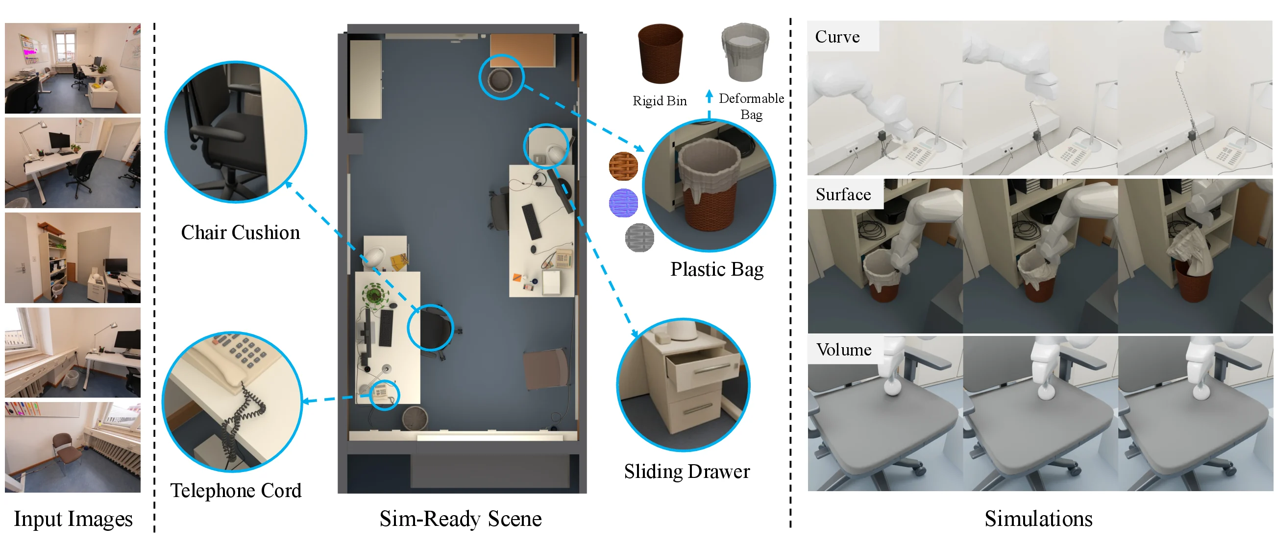
DistScene generated scene for navigation. Credit: DistScene authors. Original image ↗
DistScene investigates object-to-scene distillation for 3D generation. It uses an object generator to help create scene training data, then generates environments and objects within a shared scene frame.
A whole room introduces relationships
Object generation can produce a plausible chair without deciding where that chair belongs. A scene also needs scale, layout, and relationships between objects and the environment. A chair must fit the table; a doorway must remain traversable; objects should occupy coherent positions.
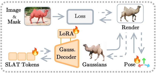
DistScene tackles the move from individual assets to a shared scene frame. Its training-data pipeline and object-level refinement address different parts of that problem. The method diagrams are useful for distinguishing how the scene is composed from how an individual object gains detail.
Build data from generated assets
The project describes a curation process in which a vision-language model produces descriptions of assets and environments. Images condition Trellis.2 generation; the resulting objects are placed into environments with physics checks, and rendering provides scene-conditioning images.
Generate globally, refine locally
At inference, the environment and objects are generated together. Each object then moves into local voxel support for scene-conditioned refinement before being returned to the scene.
This gives the method two connected concerns: the coherence of the whole environment and the detail of individual objects.
Work through local and scene coordinates
Object-level refinement is useful only if the refined object returns to the correct place in the scene. A simplified coordinate transform makes the relationship explicit. With scale s, rotation R, translation t, and a local point p, a scene-space point is:
Take an illustrative point p = (1, 0, 0), identity rotation, scale 0.5, and translation (2, 0, 0). The scene point is (2.5, 0, 0). Returning through the inverse subtracts the translation and divides by the scale, recovering (1, 0, 0). The chart varies the local x coordinate for this same simple transform. It is not the project's measured placement error or a description of every implementation detail.
A local shape can improve while a placement mistake makes the whole room less usable. Refining a chair and returning it with the wrong scale could block a doorway even if the chair itself looks better. This explains the value of a shared scene frame: object identity, scale, support, and position must remain compatible as local detail changes.
Test the space between objects
A room is more than a collection of attractive assets. For an illustrative passage 0.8 metres wide and an agent 0.6 metres wide, the total lateral clearance is 0.2 metres. If centered, that is 0.1 metres per side before accounting for body shape, collision margins, or turning. This simple difference is not a navigation success guarantee; it identifies an assumption that should be checked in the simulator.
Inspect support relationships, collisions, and routes before focusing on texture. A table can look plausible while its scale makes the chairs unusable. A door can be recognizable while the opening is blocked. A navigation demonstration should preserve both the generated scene and the collision representation used by the simulator, since a render alone does not expose the latter.
The project describes its interactive preview as compressed to approximately 10% of the original generated result. Missing detail in that preview is therefore not a direct measure of the full reconstruction's fidelity. Use the full result for detail claims and the relevant simulation artifact for navigability claims. Distinguishing those representations makes the object-to-scene contribution easier to evaluate without mistaking a thumbnail, local mesh, or compressed viewer for the complete scene.
Keep an object’s local and scene positions consistent
- Generate a scene frame
- Refine each object locally
- Apply the inverse placement transform
- Check relationships in the scene
Focus the graph and use arrow keys, or tap a point, to inspect values. The complete data table is available below.
View data table
| Local x (units) | Scene x (units) |
|---|---|
| 0 | 2 |
| 0.5 | 2.25 |
| 1 | 2.5 |
| 1.5 | 2.75 |
| 2 | 3 |
Review layout before surface detail
Open one of the project’s interactive previews and identify the major objects. Check relative scale, support surfaces, and the space available between them. Then compare the preview with the rendered result. The site describes the preview as compressed, so missing visual detail there should not automatically be attributed to the full output.
For a navigation example, follow the path through the scene. A beautiful render is weak evidence for usable free space if the viewer cannot inspect collisions or passages. Conversely, a traversable room can still contain implausible objects or inconsistent geometry.
What a release would need to establish
The project marks code, checkpoints, and its dataset as coming soon at source review. That is a research availability statement, not a ready-to-install package. Before planning an integration, look for the actual release, input requirements, asset format, and inference configuration.
For a later evaluation, retain both global and object-level checks: layout consistency, recognizable objects, navigable space, and local detail. This separates the scene-generation task from selecting a pleasing thumbnail. We have examined the public methodology and demonstrations, not reproduced the data-curation pipeline or independently benchmarked scene quality.