GenIA: aligning generated 3D objects with their observations
Test-time constraints help a frozen reconstruction model preserve geometry, appearance, and placement.
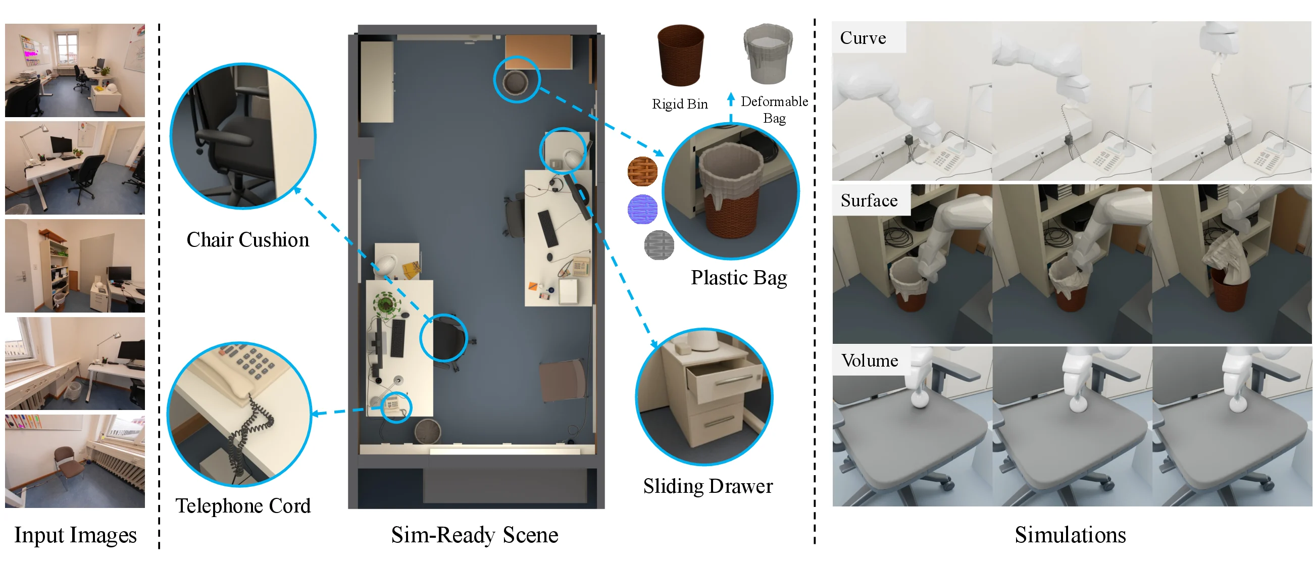
GenIA reconstruction refinement stage. Credit: GenIA authors · Meta. Original image ↗
Generative reconstruction can fill in unseen parts of an object, but the result may drift from the photographs that supplied the evidence. GenIA addresses that mismatch through test-time input alignment around a frozen SAM3D model.
Separate completing an object from matching the evidence
A generative model can produce a plausible object even when the unseen side is unknown. Reconstruction adds another requirement: the observed side must match the input, and the object must occupy a consistent pose and scale.
GenIA uses geometric and image evidence during inference to guide a frozen SAM3D model. The useful distinction is between the prior that proposes a complete object and the observations that constrain that proposal. A detailed result can still disagree with the camera image if its position, proportions, or appearance are wrong.
Ground generation in observations
The framework uses geometric and photometric constraints to align pose and appearance. It supports monocular images, multiple views, and dynamic inputs, extending beyond the foundation model’s single-view setting.
An optional refinement stage adjusts appearance and placement against the observations. The project explains these stages and provides comparisons with and without refinement.
Separate observed and unseen surfaces
A reconstruction has two kinds of information: surfaces supported by input views and surfaces completed by the generative prior. Inspect both. Strong agreement on a visible surface does not establish the accuracy of an unseen one.
Work through an alignment error
A reconstruction can have the right shape and still be misplaced. Camera projection gives a simple example. In an illustrative pinhole camera with focal length f = 800 pixels and principal point at zero, a point with X = 0.1 metres and Z = 2 metres projects to:
Changing the object's horizontal position by another 0.1 metres shifts this projected coordinate to 80 pixels at the same depth. A forty-pixel discrepancy can be a pose or placement error rather than a missing surface detail. The chart holds depth and focal length fixed while varying horizontal displacement. It is a teaching model, not GenIA's reported camera calibration or measured accuracy.
Depth also changes the interpretation. At four metres, the original X = 0.1 point projects to 20 pixels. The same world-space displacement therefore need not produce the same image-space error in different views. This helps explain why camera information and multiple observations matter. An optimizer should compare the prediction with the evidence in a compatible coordinate system rather than treating every visual discrepancy as a texture problem.
Identify which surfaces supplied evidence
Imagine a photograph of a mug that shows its handle on the right. The reconstructed mug should align with that observation before its unseen back is judged. A completed back surface can be plausible without being observed. Mark visible and inferred regions explicitly in a review, and compare the output from the original camera before relying on an attractive orbiting render.
With several input views, inspect whether one placement explains all of them. Improving one view while worsening another can expose an inconsistent pose, geometry, or camera assumption. Photometric agreement also depends on lighting and appearance; a good color match is not a complete geometric validation.
Test-time refinement introduces additional computation and can change both appearance and position. Compare refined and unrefined outputs as distinct configurations, retaining their runtime and supplied geometry. For a fair practical comparison, keep the observed cameras and input masks consistent. The goal is not to reward an output for looking detailed in isolation; it is to understand which observations constrain the generated object, which parts remain uncertain, and what extra optimization was needed to obtain the result.
A placement change becomes a pixel shift
Focus the graph and use arrow keys, or tap a point, to inspect values. The complete data table is available below.
View data table
| Horizontal displacement (m) | Image displacement (px) |
|---|---|
| 0 | 0 |
| 0.05 | 20 |
| 0.1 | 40 |
| 0.15 | 60 |
| 0.2 | 80 |
Use the input cameras as a reference
The project gallery exposes input views and reconstructions. Start by comparing the reconstructed object from an observed camera, then move to a view that was not supplied. The first comparison tests alignment; the second shows what the generator inferred about hidden regions.
Inspect silhouette, object placement, and texture separately. A texture mismatch may conceal a geometry error, while a strong silhouette can coexist with incorrect detail on the unseen side. For multiple views, check whether a feature appears in a consistent location across cameras.
Read refinement results with their cost
Test-time optimization adds work after the initial prediction. When comparing quality, record whether refinement was enabled and read the runtime measurements for the same configuration. A refined output and an unrefined baseline are different evaluation settings.
For dynamic objects, inspect consistency across time as well as across cameras. A visually smooth sequence can still drift in world-space placement. The project supports externally supplied geometry in parts of its workflow; note when that information is available, because it changes what the system has to infer.
Begin with one gallery example and its linked paper. We have examined the public methodology and demonstrations, not reproduced the reconstruction benchmarks or established correctness for arbitrary input scenes.